
TM 5-2410-240-23-2
0044
INSTALLATION CONTINUED
N OT E
Remove caps from hoses and plugs from gear motor.
Install hoses as noted during removal.
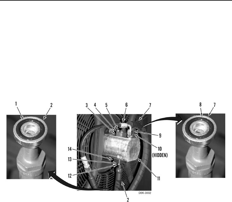
11. Install new O-ring (Figure 16, Item 1) on hose (Figure 16, Item 2).
12. Install hose (Figure 16, Item 2), flange (Figure 16, Item 14), four washers (Figure 16, Item 13), and bolts
(Figure 16, Item 12) on gear motor (Figure 16, Item 11).
13. Install new O-ring (Figure 16, Item 8) on hose (Figure 16, Item 7).
14. Install hose (Figure 16, Item 7), flange (Figure 16, Item 3), four washers (Figure 16, Item 4), and bolts
(Figure 16, Item 5) on gear motor (Figure 16, Item 11).
15. Install new O-ring (Figure 16, Item 10) and connect hose (Figure 16, Item 6) on gear motor (Figure 16, Item 11)
and tighten fitting (Figure 16, Item 9).
Figure 16. Gear Motor, Hoses, O-rings, and Retaining Hardware.
0044