
TM 5-2410-240-23-2
0046
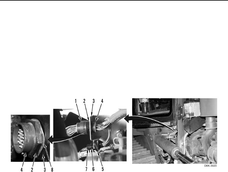
ENGINE MAIN HARNESS INSTALLATION
00046
N OT E
Install electrical connectors as noted during removal.
1. Install engine harness (Figure 32, Item 6) on machine.
2. Connect and lock platform harness (Figure 32, Item 7) on engine harness (Figure 32, Item 6).
3. Install new tiedown strap (Figure 32, Item 5) on plate (Figure 32, Item 3).
4. Install engine harness (Figure 32, Item 4) on plate (Figure 32, Item 3).
5. Install washer (Figure 32, Item 8) and nut (Figure 32, Item 2) retaining engine harness (Figure 32, Item 4) on
plate (Figure 32, Item 3).
6. Connect and lock platform two platform harness connectors (Figure 32, Item 1) to two engine harness
connectors (Figure 32, Item 4).
Figure 32. Engine Harness and Platform Harness.
0046