• Home
  • Download PDF
  • Order CD-ROM
  • Order in Print
Figure 33. Engine Harness at Fan Control Manifold.
Figure 35. Engine Harness Connector Behind Right Side of Flywheel Housing.

Field Maintenance Manual 2 D6K Dozer Type I With Winch and Type II With Ripper
Page Navigation
  132    133    134    135    136  137  138    139    140    141    142  
img
.
TM 5-2410-240-23-2
0046
ENGINE MAIN HARNESS INSTALLATION CONTINUED
N OT E
Install engine harness as noted during removal.
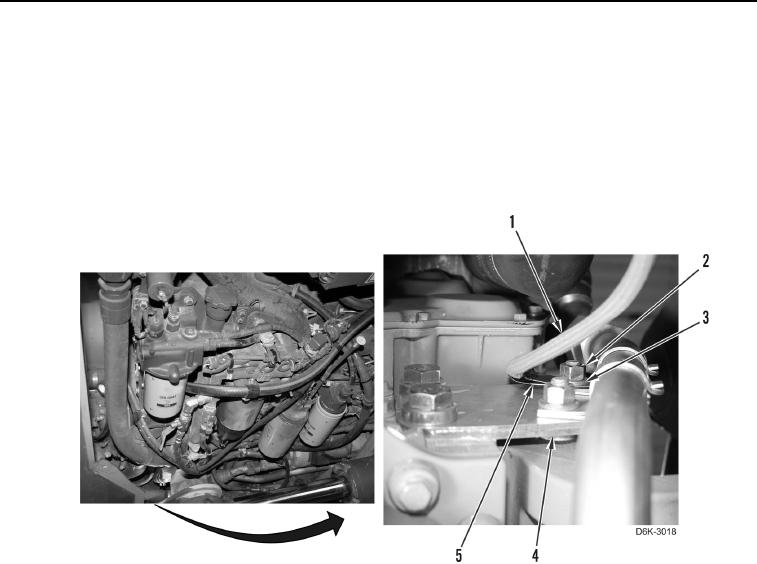
14. Install clamp (Figure 34, Item 5) on engine harness (Figure 34, Item 1).
15. Install clamp (Figure 34, Item 5), washer (Figure 34, Item 3), and nut (Figure 34, Item 2) on plate (Figure 34,
Item 4).
Figure 34. Engine Harness Retainer at Front Left Side of Engine.
0046
0046-30


Privacy Statement
Press Release
Contact

© Copyright Integrated Publishing, Inc.. All Rights Reserved.