
TM 5-2410-240-23-2
0046
ENGINE MAIN HARNESS INSTALLATION CONTINUED
N OT E
Install bolts and spacers as noted during removal.
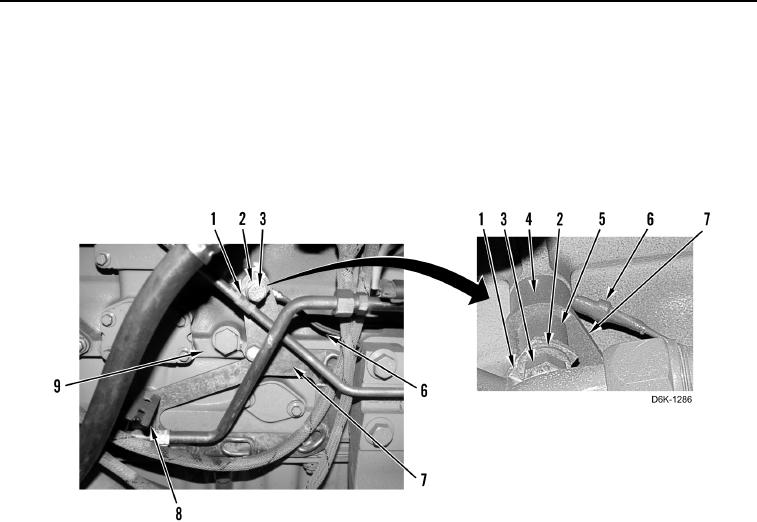
24. Install ground wire (Figure 39, Item 6), spacer (Figure 39, Item 4), bracket (Figure 39, Item 7), two spacers
(Figure 39, Item 5), one harness bracket (Figure 39, Item 8), two line clips (Figure 39, Item 1), three washers
(Figure 39, Item 2), and bolts (Figure 39, Item 3) on engine (Figure 39, Item 9).
Figure 39. Side Engine Bracket.
0046