
TM 5-2410-240-23-2
0046
ENGINE MAIN HARNESS INSTALLATION CONTINUED
36. Install harness (Figure 45, Item 1), ground strap (Figure 45, Item 3), and stud (Figure 45, Item 2) on engine
(Figure 45, Item 4).
Figure 45. Ground Cables.
0046
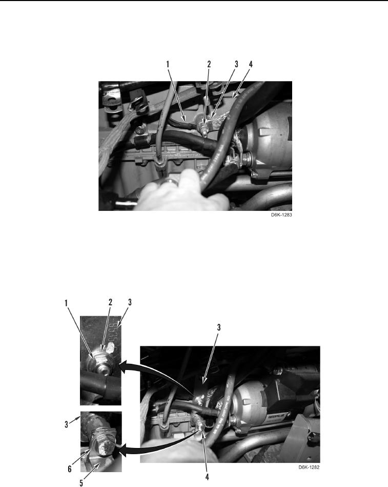
37. Install bracket (Figure 46, Item 3), washer (Figure 46, Item 2), and nut (Figure 46, Item 1) on machine.
38. Install clamp (Figure 46, Item 5), washer (Figure 46, Item 6), and bolt (Figure 46, Item 4) on bracket
(Figure 46, Item 3).
Figure 46. Cooler Line Support Bracket.
0046