
TM 5-2410-240-23-2
0046
ENGINE MAIN HARNESS INSTALLATION CONTINUED
N OT E
Install tiedown straps as noted during removal.
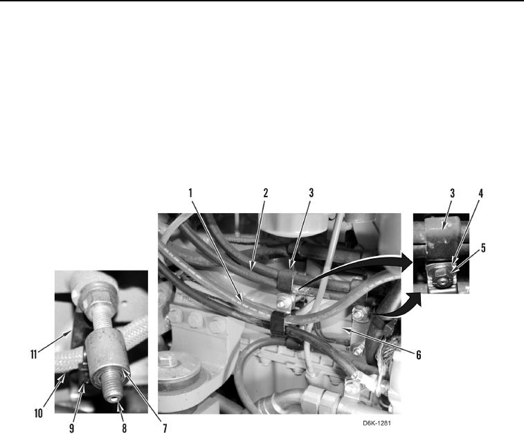
39. Install bracket (Figure 47, Item 11) and stud (Figure 47, Item 8) on engine (Figure 47, Item 6).
40. Install new tiedown strap (Figure 47, Item 9) on harness (Figure 47, Item 10).
41. Position two cables (Figure 47, Item 1) and three hoses (Figure 47, Item 2) on engine (Figure 47, Item 6).
42. Install two spacers (Figure 47, Item 7), five clamps (Figure 47, Item 3), two washers (Figure 47, Item 4), and
nuts (Figure 47, Item 5) on engine (Figure 47, Item 6).
Figure 47. Left Side of Engine Hoses and Cables.
0046