
TM 5-2410-240-23-2
0046
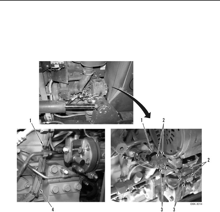
ENGINE MAIN HARNESS INSTALLATION CONTINUED
N OT E
Install engine harness and tiedown straps, and connect electrical connectors as noted
during removal.
25. Connect four engine harness connectors (Figure 40, Item 3) on A/C system connectors (Figure 40, Item 2).
26. Install 14 new tiedown straps (Figure 40, Item 1) on engine harness (Figure 40, Item 4).
Figure 40. Engine Harness Retainers and A/C System Connectors on Right Side of Engine.
0046