
TM 5-2410-240-23-2
0079
REMOVAL CONTINUED
WARN I N G
Lubricating/hydraulic oils used in the performance of maintenance can be very slippery.
Immediately wipe up any spills. Failure to follow this warning may result in injury to
personnel.
12. Position drain pan underneath machine.
N OT E
Tag and mark oil line and drain tube to aid installation.
Cap open end on oil line and drain tube.
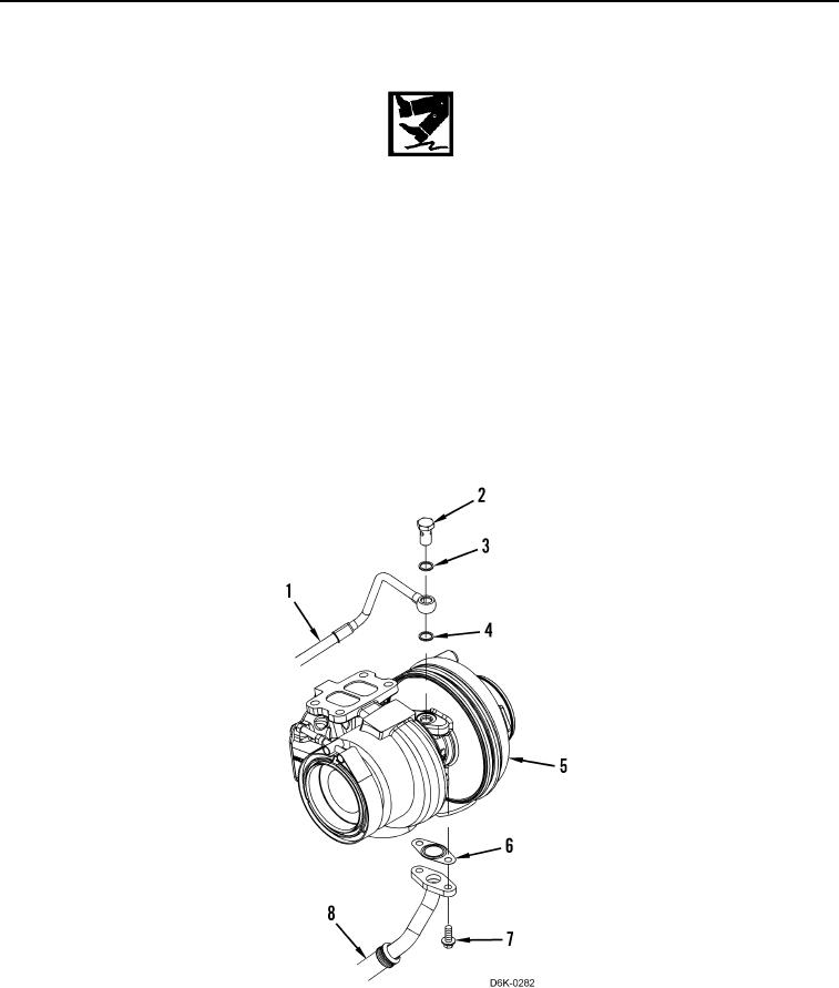
13. Remove two bolts (Figure 5, Item 7), drain tube (Figure 5, Item 8), and gasket (Figure 5, Item 6) from
turbocharger (Figure 5, Item 5). Discard gasket.
14. Remove fluid passage bolt (Figure 5, Item 2), washer (Figure 5, Item 3), oil line (Figure 5, Item 1), and washer
(Figure 5, Item 4) from turbocharger (Figure 5, Item 5). Position oil line aside and discard washers.
Figure 5. Turbocharger, Oil Line, and Drain Tube.
0079