
TM 5-2410-240-23-2
0079
REMOVAL CONTINUED
N OT E
Tag and mark hoses to aid installation.
Cap hose ends.
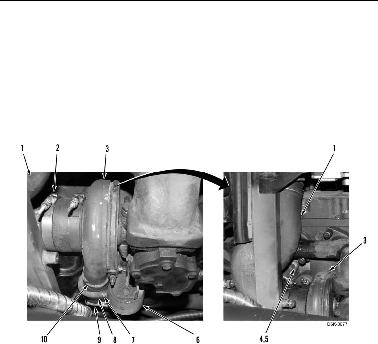
8. Loosen clamp (Figure 4, Item 2).
9. Release clamp (Figure 4, Item 7) and remove hose (Figure 4, Item 8) from wastegate (Figure 4, item 6).
10. Loosen two clamps (Figure 4, Item 9) and remove hose (Figure 4, Item 10) from turbocharger (Figure 4,
Item 3).
11. Remove three bolts (Figure 4, Item 4) and washers (Figure 4, Item 5) retaining air inlet elbow (Figure 4, Item 1)
on engine. Position air inlet elbow aside.
Figure 4. Turbocharger and Wastegate.
0079