
TM 5-2410-240-23-2
0078
INSTALLATION CONTINUED
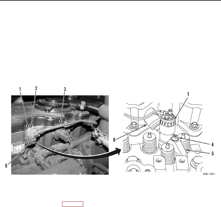
5. Install six new cylinder sleeves (Figure 7, Item 6) on six fuel injectors (Figure 7, Item 1). Ensure that flange of
seal is flush with valve cover base.
C AU T I O N
Ensure the ends of the fuel injection line are seated in the fuel injector and fuel manifold.
Failure to follow this caution may cause engine damage.
6. Install six new fuel injector lines (Figure 7, Item 3) with new seals (Figure 7, Item 2) on six fuel injectors
(Figure 7, Item 1) finger tight.
7. Tighten six machine bolts (Figure 7, Item 4) on six injector clamps (Figure 7, Item 5) to 20 lb-ft (27.1 Nm).
8. Tighten fuel injection line (Figure 7, Item 3) to 22 lb-ft (30 Nm).
Figure 7. Fuel Injector Fuel Line Replacement.
0078
FOLLOW-ON TASKS
00078
1. Install rocker arm assembly (WP 0102).
2. Purge fuel system (TM 5-2410-240-10).
3. Load trim files on exchanged injectors (WP 0026).
4. Verify correct operation of machine (TM 5-2410-240-10).
END OF TASK
END OF WORK PACKAGE
0078-7/(8 blank)