
TM 5-2410-240-23-2
0089
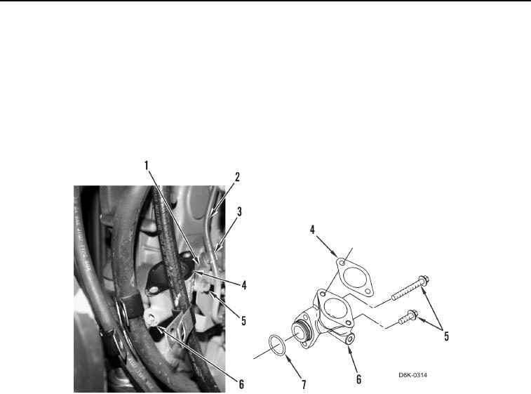
REMOVAL CONTINUED
6. Remove gasket (Figure 3, Item 4) from oil fill housing (Figure 3, Item 6), and remove hose (Figure 3, Item 2)
from clip (Figure 3, Item 3) and position aside. Discard gasket.
N OT E
Note length and position of bolts to aid installation.
7. Remove two bolts (Figure 3, Item 5), bracket (Figure 3, Item 1), oil fill housing (Figure 3, Item 6), and O-ring
(Figure 3, Item 7) from machine. Discard O-ring.
Figure 3. Oil Fill Housing.
0089
END OF TASK
CLEANING AND INSPECTION
00089
Clean and inspect all parts IAW Mechanical General Maintenance Instructions (WP 0282).
END OF TASK
INSTALLATION
00089
N OT E
Install bolts as noted during removal.
1. Install new O-ring (Figure 3, Item 7), oil fill housing (Figure 3, Item 6), bracket (Figure 3, Item 1), and two bolts
(Figure 3, Item 5).
2. Position hose (Figure 3, Item 2) on clip (Figure 3, Item 3), and install new gasket (Figure 3, Item 4) on oil fill
housing (Figure 3, Item 6).
3. Install oil fill tube (Figure 4, Item 4) on oil fill housing (Figure 4, Item 5) and two bolts (Figure 4, Item 2) on
machine.