
TM 5-2410-240-23-2
0092
REMOVAL CONTINUED
N OT E
Tag and mark all electrical connectors and note harness routing to aid installation.
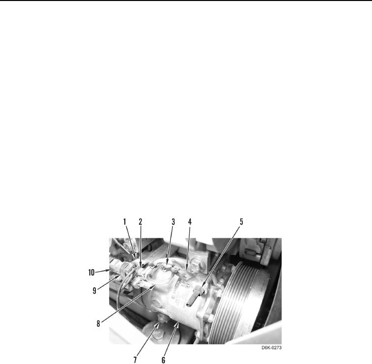
7. Remove tiedown strap (Figure 2, Item 9) from bracket (Figure 2, Item 1). Discard tiedown strap.
8. Disconnect electrical connector (Figure 2, Item 2) from wiring harness (Figure 2, Item 10).
N OT E
Note position of bracket to aid installation.
9. Remove two bolts (Figure 2, Item 7) and bracket (Figure 2, Item 1) from A/C compressor (Figure 2, Item 6).
10. Remove tiedown strap (Figure 2, Item 3) from bracket (Figure 2, Item 4) and position harness (Figure 2,
Item 8) aside. Discard tiedown strap.
N OT E
Studs will not remove from compressor until compressor is removed.
11. Fully loosen two studs (Figure 2, Item 5) and remove A/C compressor (Figure 2, Item 6) from machine.
Figure 2. A/C Compressor Wiring Harness.
0092