
TM 5-2410-240-23-2
0092
INSTALLATION CONTINUED
N OT E
Install bracket as noted during removal.
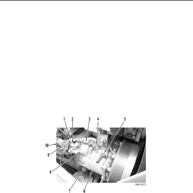
7. Install A/C compressor (Figure 5, Item 6) and studs (Figure 5, Item 5) on machine. Position bracket (Figure 5,
Item 4) before tightening studs.
8. Position harness (Figure 5, Item 8) on bracket (Figure 5, Item 4) and install new tiedown strap (Figure 5,
Item 3) on bracket.
N OT E
Install bracket as noted during removal.
9. Install bracket (Figure 5, Item 1) and two bolts (Figure 5, Item 7) on A/C compressor (Figure 5, Item 6).
N OT E
Install wires and wiring harnesses as noted during removal.
10. Connect electrical connector (Figure 5, Item 2) on wiring harness (Figure 5, Item 10).
11. Install new tiedown strap (Figure 5, Item 9) on bracket (Figure 5, Item 1).
Figure 5. A/C Compressor Wiring Harness.
0092