
10
TM 5-2410-240-23-2
FIELD MAINTENANCE
-
FLYWHEEL HOUSING REPLACEMENT
0098
Removal, Cleaning and Inspection, Installation
INITIAL SETUP
Personnel Required
Tools and Special Tools
0
0
Tool Kit, General Mechanic's
Two
0
(WP 0289, Item 51)
0
References
0
Bracket, Link (2,250-lb [1,020-kg] lifting
WP 0282
capacity) (WP 0289, Item 8)
0
0
Guide Stud (8 mm x 51 mm) (2)
Equipment Conditions
0
(WP 0289, Item 24)
0
Machine parked (TM-2410-240-10)
0
Wrench, Torque, Click, Ratcheting, 1/2" Drive,
Flywheel assembly removed (WP 0097)
250 lb-ft (WP 0289, Item 57)
0
0
Wrench, Torque, Click, Ratcheting, 3/8" Drive,
Drawings Required
0
75 lb-ft (WP 0289, Item 59)
0
TM 5-2410-240-24P, Figure 36
0
Lifting device (1,000-lb capacity)
0
Estimated Time to Complete
0
Materials/Parts
0
1.0 Hr
0
Rag, wiping (WP 0290, Item 21)
0
REMOVAL
00098
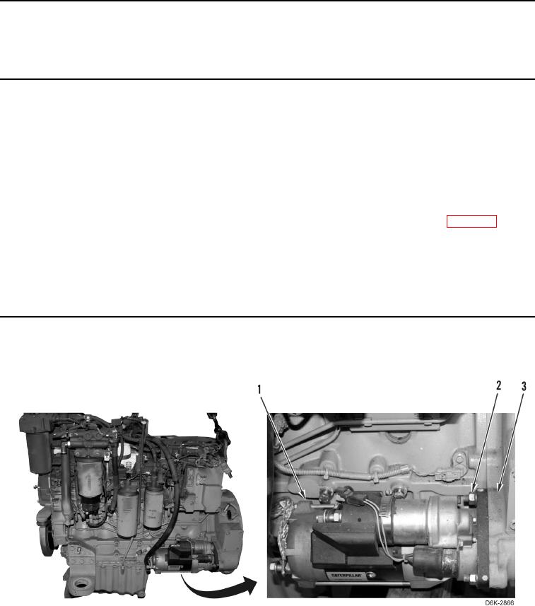
1. Remove three nuts (Figure 1, Item 2) and starter (Figure 1, Item 1) from flywheel housing (Figure 1, Item 3).
Figure 1. Starter and Retaining Hardware.
0098