
TM 5-2410-240-23-2
0134
REMOVAL CONTINUED
N OT E
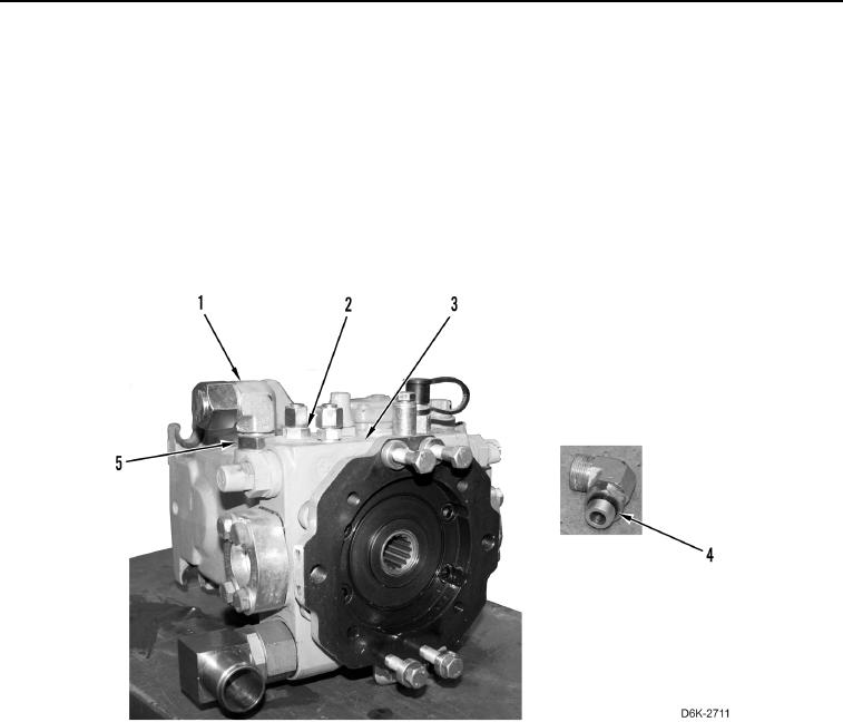
Note location of elbows and fittings to aid installation.
Note orientation of elbows to aid installation.
33. Remove five fittings (Figure 14, Item 2) from right hydrostatic piston pump (Figure 14, Item 3).
34. Loosen three nuts (Figure 14, Item 5) and remove elbows (Figure 14, Item 1) from right hydrostatic piston
pump (Figure 14, Item 3).
35. Remove 14 O-rings (Figure 14, Item 4) from three elbows (Figure 14, Item 1) and five fittings (Figure 14,
Item 2). Discard O-rings.
Figure 14. Elbows, Fittings, and O-rings on Right Hydraulic Piston Pump.
0134
END OF TASK
CLEANING AND INSPECTION
000134
Clean and inspect all components IAW Mechanical General Maintenance Instructions (WP 0282).
END OF TASK