
TM 5-2410-240-23-2
0134
INSTALLATION CONTINUED
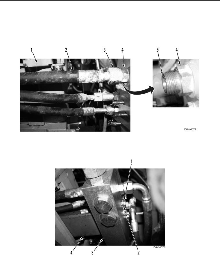
10. Apply lubricating oil on three new O-rings (Figure 18, Item 5).
11. Install three new O-rings (Figure 18, Item 5) on three fittings (Figure 18, Item 4).
12. Route three hoses (Figure 18, Item 2) under drive pump (Figure 18, Item 1).
13. Install three hoses (Figure 18, Item 2) on three fittings (Figure 18, Item 4) and tighten tube nuts (Figure 18,
Item 3).
Figure 18. Transmission Control Valve Hydraulic Hoses.
0134
14. Install valve transmission control mounting bracket (Figure 19, Item 4) to transmission control valve (Figure 19,
Item 3).
Figure 19. Transmission Control Valve Mounting Bracket.
0134
15. Install three washers (Figure 19, Item 2) and bolts (Figure 19, Item 1) on transmission control valve
(Figure 19, Item 3).
16. Tighten three bolts (Figure 19, Item 1).