
TM 5-2410-240-23-2
0134
INSTALLATION CONTINUED
N OT E
Remove caps or plugs from tubes and fittings.
Install tubes as noted during removal.
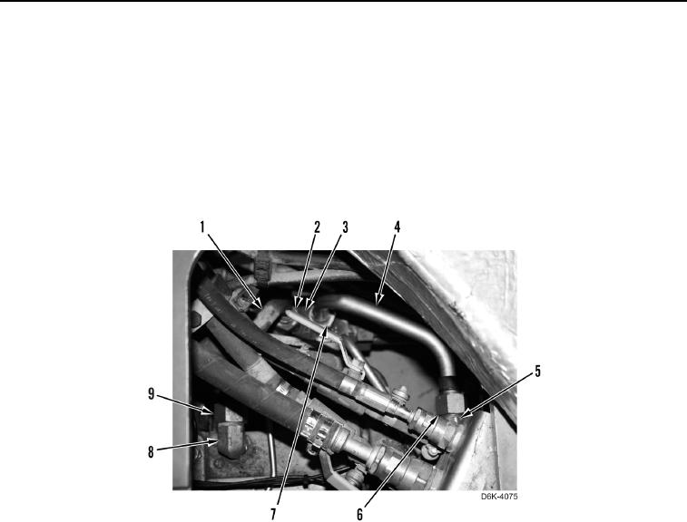
33. Connect tube (Figure 24, Item 1) on fitting (Figure 24, Item 8) and transmission control manifold (Figure 24,
Item 3) and tighten two tube nuts (Figure 24, Items 9 and 2).
34. Connect tube (Figure 24, Item 4) on fitting (Figure 24, Item 5) and transmission control manifold (Figure 24,
Item 3) and tighten two tube nuts (Figure 24, Items 6 and 7).
Figure 24. Tubes on Left and Right Hydrostatic Drive Piston Pump and Transmission Control Manifold.
0134