
TM 5-2410-240-23-2
0134
INSTALLATION CONTINUED
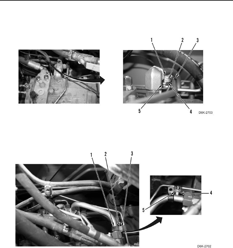
36. Position two clamps (Figure 26, Item 3) and install washer (Figure 26, Item 2), bolt (Figure 26, Item 1), washer
(Figure 26, Item 4), and nut (Figure 26, Item 5) on two clamps.
Figure 26. Tube Retaining Hardware on Right Hydrostatic Drive Piston Pump.
0134
37. Position two clamps (Figure 27, Item 1) and install washer (Figure 27, Item 3), bolt (Figure 27, Item 2), washer
(Figure 27, Item 5), and nut (Figure 27, Item 4) on two clamps.
Figure 27. Tube Retaining Hardware on Left Hydrostatic Drive Piston Pump.
0134