
TM 5-2410-240-23-2
0135
REMOVAL CONTINUED
N OT E
Tag and cap all hoses and lines to aid installation.
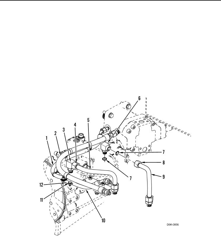
6. Remove bolt (Figure 3, Item 11) from bracket (Figure 3, Item 12).
7. Remove hose (Figure 3, Item 1), and hose (Figure 3, Item 2) from under pump (Figure 3, Item 10). Position
hoses aside.
8. Loosen tube nut (Figure 3, Item 4) and remove line (Figure 3, Item 5) from machine.
9. Remove fitting (Figure 3, Item 3) from pump (Figure 3, Item 10).
10. Loosen tube nut (Figure 3, Item 8) and remove line (Figure 3, Item 9) from machine.
11. Remove fitting (Figure 3, Item 6) from pump (Figure 3, Item 10).
12. Remove four O-rings (Figure 3, Item 7) from two fittings (Figure 3, Items 3 and 6). Discard O-rings.
Figure 3. Drain Hoses.
0135