
TM 5-2410-240-23-2
0135
REMOVAL CONTINUED
N OT E
Tag and cap all hoses and lines to aid installation.
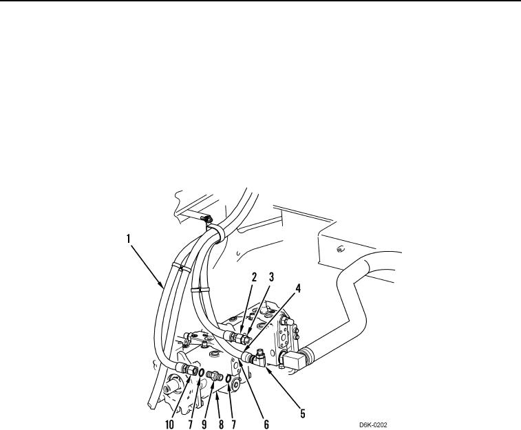
17. Loosen two tube nuts (Figure 5, Items 2 and 10) and remove hoses (Figure 5, Items 1 and 6) from fittings
(Figure 5, Items 3 and 9).
18. Disconnect hose (Figure 5, Item 4) from coupling (Figure 5, Item 5). Position hoses aside.
19. Remove two fittings (Figure 5, Items 3 and 9) and coupling (Figure 5, Item 5) from pump (Figure 5, Item 8).
20. Remove four O-rings (Figure 5, Item 7) from two fittings (Figure 5, Items 3 and 9). Discard O-rings.
Figure 5. Pump Hose.
0135