
TM 5-2410-240-23-2
0135
REMOVAL CONTINUED
N OT E
Tag and cap all hoses and lines to aid installation.
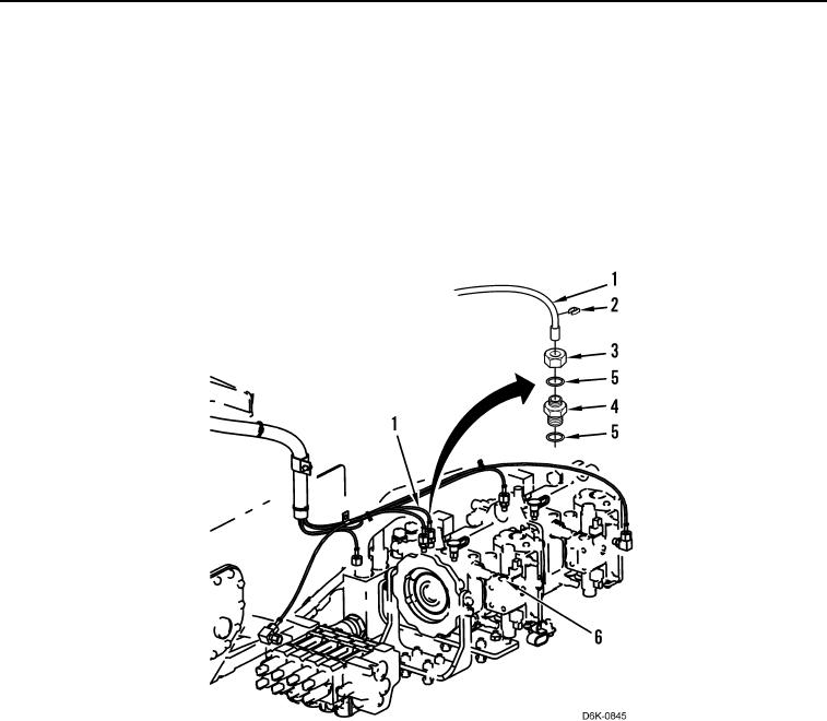
3. Loosen four tube nuts (Figure 2, Item 3) and remove four lines (Figure 2, Item 1) and markers (Figure 2,
Item 2), from fittings (Figure 2, Item 4). Position lines aside.
4. Remove four fittings (Figure 2, Item 4) from pump (Figure 2, Item 6).
5. Remove eight O-rings (Figure 2, Item 5) from four fittings (Figure 2, Item 5). Discard O-rings.
Figure 2. Diagnostic Lines.
0135