
TM 5-2410-240-23-2
0134
INSTALLATION CONTINUED
N OT E
Remove caps or plugs from hoses, lines, and fittings.
Install hoses and lines as noted during removal.
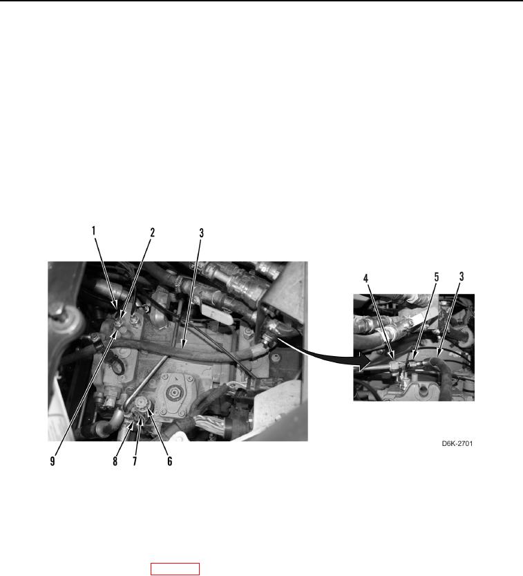
38. Connect hose (Figure 28, Item 3) on fitting (Figure 28, Item 4) and tighten tube nut (Figure 28, Item 5).
39. Connect two lines (Figure 28, Item 1) on fittings (Figure 28, Item 9) and tighten tube nuts (Figure 28, Item 2).
N OT E
Install electrical connectors and tiedown straps as noted during removal.
40. Connect harness (Figure 28, Item 7) on solenoid (Figure 28, Item 6).
41. Install new tiedown strap (Figure 28, Item 8) on harness (Figure 28, Item 7) and solenoid (Figure 28, Item 6).
Figure 28. Harness, Lines, and Hose Connections on Left and Right Hydrostatic Drive Piston Pump.
0134
END OF TASK
FOLLOW-ON TASKS
000134
1. Install winch piston pump (WP 0267).
2. Install middle bottom guards (WP 0156).
3. Install front floor plate (WP 0205).
4. Verify correct operation of machine (TM 5-2410-240-10).
END OF TASK
END OF WORK PACKAGE
0134-25/(26 blank)