
TM 5-2410-240-23-2
0134
INSTALLATION CONTINUED
N OT E
Remove caps or plugs from hoses, fittings, and open ports.
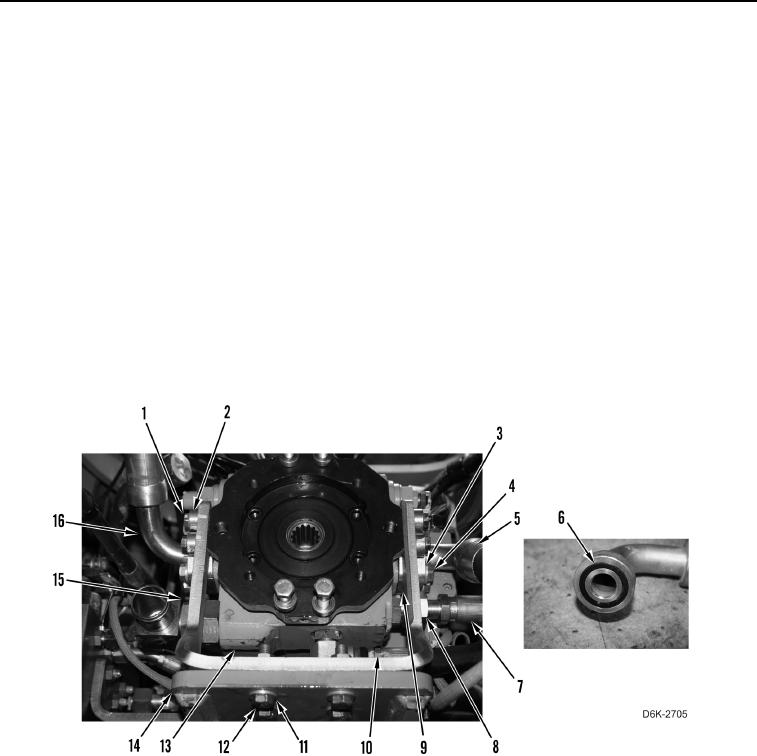
Install hoses as noted during removal.
25. Connect hose (Figure 23, Item 10) on right hydrostatic drive piston pump (Figure 23, Item 13).
26. Connect hose (Figure 23, Item 7) on right hydrostatic drive piston pump (Figure 23, Item 13) and tighten tube
nut (Figure 23, Item 8).
27. Apply lubricating oil on two new O-rings (Figure 23, Item 6).
28. Install two new O-rings (Figure 23, Item 6) on hoses (Figure 23, Items 5 and 16).
29. Install two hoses (Figure 23, Items 5 and 16), four clamps (Figure 23, Item 9), eight washers (Figure 23,
Item 3), and bolts (Figure 23, Item 4) on right hydrostatic drive piston pump (Figure 23, Item 13).
30. Position bracket (Figure 23, Item 15) on right hydrostatic drive piston pump (Figure 23, Item 13) and pump
support (Figure 23, Item 14).
31. Install four washers (Figure 23, Item 11) and bolts (Figure 23, Item 12) on pump support (Figure 23, Item 14).
32. Install four spacers (Figure 23, Item 2) and bolts (Figure 23, Item 1) on bracket (Figure 23, Item 15).
Figure 23. Retaining Hardware and Hoses on Right Hydrostatic Piston Pump.
0134