
TM 5-2410-240-23-2
0144
REMOVAL CONTINUED
N OT E
Note location of tiedown straps and tag and mark electrical connectors to aid installation.
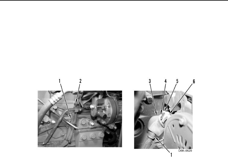
21. Remove 13 tiedown straps (Figure 8, Item 2) from harness (Figure 8, Item 1). Discard tiedown straps.
22. Position boot (Figure 8, Item 3) aside.
23. Remove nut (Figure 8, Item 4), two washers (Figure 8, Item 6), and harness (Figure 8, Item 1) from alternator
(Figure 8, Item 5).
24. Remove harness (Figure 8, Item 1) from machine.
Figure 8. Harness Retainers on Right Side of Engine and Cable Connection at Alternator.
0144
END OF TASK
CLEANING AND INSPECTION
000144
Clean and inspect all components IAW Mechanical General Maintenance Instructions (WP 0282).
END OF TASK
INSTALLATION
000144
N OT E
Install tiedown straps and electrical connectors as noted during removal.
1. Install harness (Figure 8, Item 1) on machine.
2. Install harness (Figure 8, Item 1), two washers (Figure 8, Item 6), and nut (Figure 8, Item 4) on alternator
(Figure 8, Item 5).
3. Install boot (Figure 8, Item 3) on harness (Figure 8, Item 1).
4. Install 13 tiedown straps (Figure 8, Item 2) on harness (Figure 8, Item 1).