
TM 5-2410-240-23-2
0144
REMOVAL CONTINUED
N OT E
Note location of tiedown straps and tag and mark electrical connectors to aid installation.
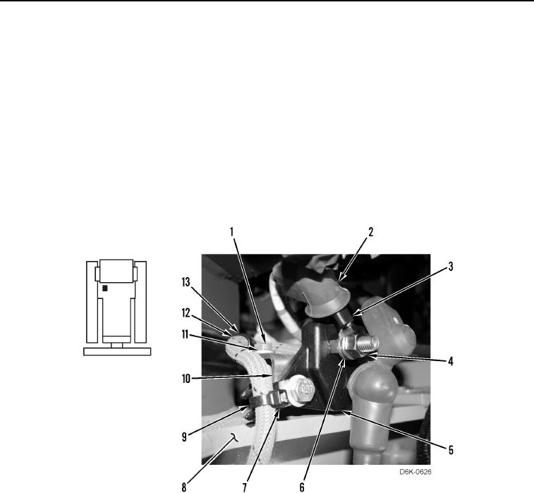
10. Remove tiedown strap (Figure 4, Item 9) from harness (Figure 4, Item 12) and from clip (Figure 4, Item 7).
Discard tiedown strap.
11. Position boot (Figure 4, Item 2) aside.
12. Remove nut (Figure 4, Item 4), washer (Figure 4, Item 6), and cable (Figure 4, Item 3) from junction block
(Figure 4, Item 5).
13. Remove bolt (Figure 4, Item 1), washer (Figure 4, Item 11), clamp (Figure 4, Item 13), bracket (Figure 4,
Item 10), and junction block (Figure 4, Item 5) from machine (Figure 4, Item 8).
14. Remove clamp (Figure 4, Item 13) from harness (Figure 4, Item 12).
Figure 4. Harness Retainer and Cable Connection at Junction Box.
0144