
TM 5-2410-240-23-2
0143
INSTALLATION CONTINUED
N OT E
Install electrical connectors as noted during removal.
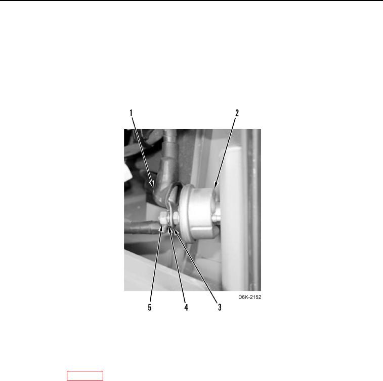
4. Install cable (Figure 5, Item 3), new lockwasher (Figure 5, Item 4), and nut (Figure 5, Item 5) on battery
disconnect switch (Figure 5, Item 2).
5. Install boot (Figure 5, Item 1) on cable (Figure 5, Item 3).
Figure 5. Cable Connection at Battery Disconnect Switch.
0143
END OF TASK
FOLLOW-ON TASKS
000143
1. Install batteries (WP 0142).
2. Verify correct operation of machine (TM 5-2410-240-10).
END OF TASK
END OF WORK PACKAGE