
TM 5-2410-240-23-2
0143
INSTALLATION
000143
N OT E
Install electrical connectors as noted during removal.
1. Install washer (Figure 3, Item 4), cable (Figure 3, Item 1), washer (Figure 3, Item 5), and nut (Figure 3, Item 6)
on junction block (Figure 3, Item 3).
2. Install boot (Figure 3, Item 2) on cable (Figure 3, Item 1).
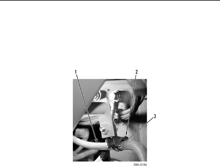
3. Install new tiedown strap (Figure 4, Item 3) on cable (Figure 4 Item 1) and anchor (Figure 4, Item 2).
Figure 4. Cable Retainer Below Junction Box.
0143