
TM 5-2410-240-23-2
0144
INSTALLATION CONTINUED
N OT E
Install tiedown straps and install electrical connectors as noted during removal.
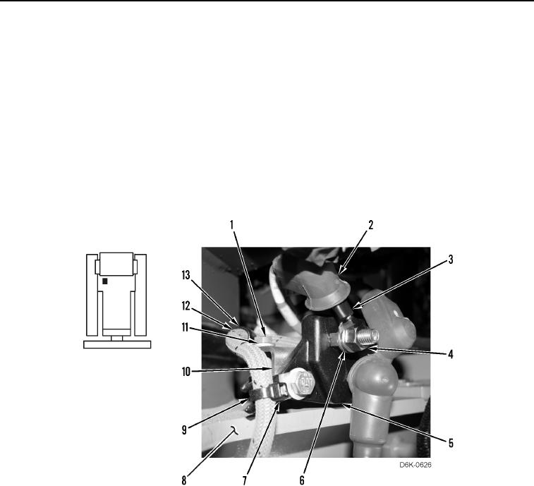
11. Install clamp (Figure 12, Item 13) on harness (Figure 12, Item 12).
12. Install junction block (Figure 12, Item 5), bracket (Figure 12, Item 10), clamp (Figure 12, Item 13), washer
(Figure 12, Item 11), and bolt (Figure 12, Item 1) on machine (Figure 12, Item 8).
13. Install cable (Figure 12, Item 3), washer (Figure 12, Item 6), and nut (Figure 12, Item 4) on junction block
(Figure 12, Item 5).
14. Install boot (Figure 12, Item 2) on cable (Figure 12, Item 3).
15. Install tiedown strap (Figure 12, Item 9) on harness (Figure 12, Item 12) and clip (Figure 12, Item 7).
Figure 12. Harness Retainer and Cable Connection at Junction Box.
0144