
TM 5-2410-240-23-2
0144
INSTALLATION CONTINUED
N OT E
Install electrical connectors as noted during removal.
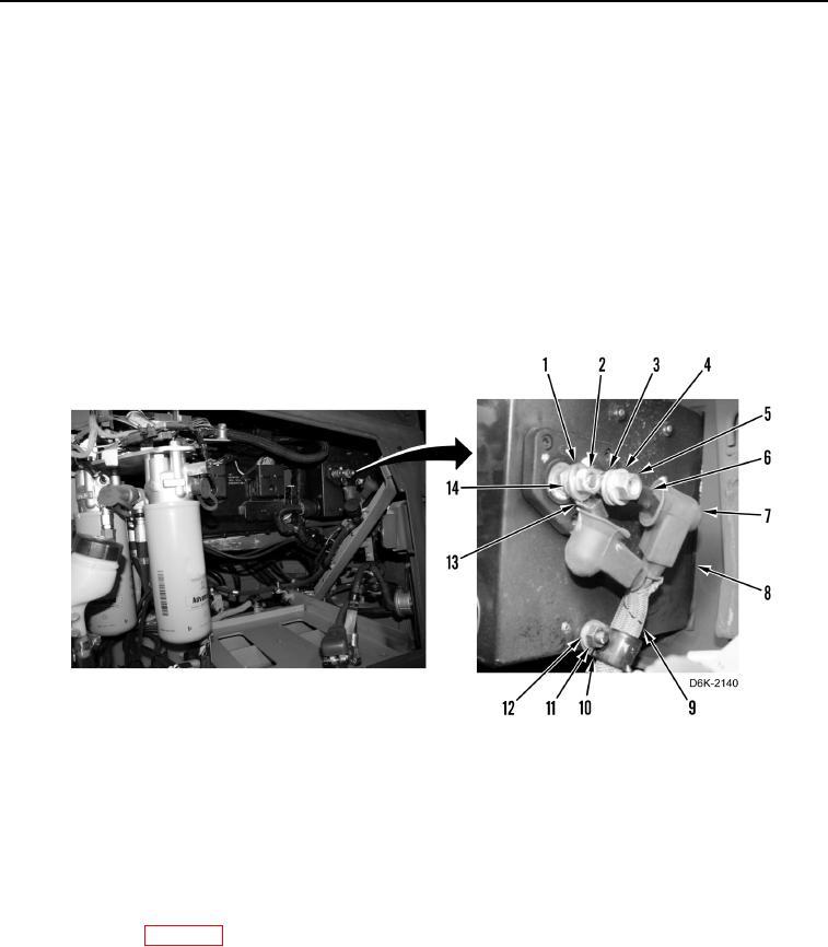
20. Install clamp (Figure 15, Item 10) on harness (Figure 15, Item 9).
21. Install clamp (Figure 15, Item 10), washer (Figure 15, Item 12), and nut (Figure 15, Item 11) on junction box
(Figure 15, Item 8).
22. Install washer (Figure 15, Item 14), cable (Figure 15, Item 13), washer (Figure 15, Item 1), and nut (Figure 15,
Item 2) on junction box (Figure 15, Item 8).
23. Install washer (Figure 15, Item 3), cable (Figure 15, Item 6), washer (Figure 15, Item 4), and nut (Figure 15,
Item 5) on junction box (Figure 15, Item 8).
24. Install two boots (Figure 15, Item 7) on cable (Figure 15, Item 13) and cable (Figure 15, Item 6).
Figure 15. Cable Connections at Junction Box.
0144
END OF TASK
FOLLOW-ON TASKS
000144
1. Install right engine access panel (WP 0182).
2. Install rear floor plate (WP 0205).
3. Install front floor plate (WP 0205).
4. Install batteries (WP 0142).
5. Verify correct operation of machine (TM 5-2410-240-10).
END OF TASK
END OF WORK PACKAGE