
TM 5-2410-240-23-2
0145
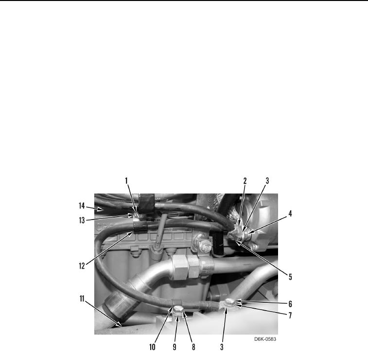
REMOVAL CONTINUED
N OT E
Tag and mark electrical connectors to aid installation.
17. Remove nut (Figure 8, Item 5), cable (Figure 8, Item 2), and cable (Figure 8, Item 3) from starter (Figure 8,
Item 4).
18. Remove bolt (Figure 8, Item 1), washers (Figure 8, Item 13), and clamp (Figure 8, Item 12) from engine
(Figure 8, Item 14).
19. Remove clamp (Figure 8, Item 12) from cable (Figure 8, Item 3).
20. Remove bolt (Figure 8, Item 8), washer (Figure 8, Item 9), and clamp (Figure 8, Item 10) from machine
(Figure 8, Item 11).
21. Remove clamp (Figure 8, Item 10) from cable (Figure 8, Item 3).
22. Remove bolt (Figure 8, Item 6), washer (Figure 8, Item 7), and cable (Figure 8, Item 3) from machine (Figure 8,
Item 11).
Figure 8. Cable Connection and Retaining Hardware at Starter.
0145
END OF TASK
CLEANING AND INSPECTION
000145
Clean and inspect all components IAW Mechanical General Maintenance Instructions (WP 0282).
END OF TASK