
TM 5-2410-240-23-2
0145
INSTALLATION
000145
N OT E
Install electrical connectors as noted during removal.
1. Install cable (Figure 8, Item 3), washer (Figure 8, Item 7), and bolt (Figure 8, Item 6) on machine (Figure 8,
Item 11).
2. Install clamp (Figure 8, Item 10) on cable (Figure 8, Item 3).
3. Install clamp (Figure 8, Item 10), washer (Figure 8, Item 9), and bolt (Figure 8, Item 8) on machine (Figure 8,
Item 11).
4. Install clamp (Figure 8, Item 12) on cable (Figure 8, Item 3).
5. Install clamp (Figure 8, Item 12), washers (Figure 8, Item 13), and bolt (Figure 8, Item 1) on engine (Figure 8,
Item 14).
6. Install cable (Figure 8, Item 3), cable (Figure 8, Item 2), and nut (Figure 8, Item 5) on starter (Figure 8, Item 4).
N OT E
Install electrical connectors as noted during removal.
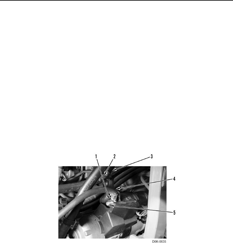
7. Install cable (Figure 9, Item 3) on machine.
8. Install cable (Figure 9, Item 3), cable (Figure 9, Item 4), and nut (Figure 9, Item 1) on starter (Figure 9, Item 5).
9. Install boot (Figure 9, Item 2) on cable (Figure 9, Item 4) and cable (Figure 9, Item 3).
Figure 9. Cable Connection at Starter.
0145