
TM 5-2410-240-23-2
0145
INSTALLATION CONTINUED
N OT E
Tag and mark electrical connectors to aid installation.
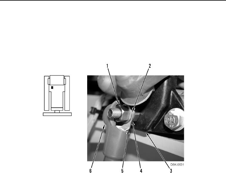
21. Install washer (Figure 15, Item 4), cable (Figure 15, Item 5), washer (Figure 15, Item 2), and nut (Figure 15,
Item 1) on junction box (Figure 15, Item 3).
22. Install boot (Figure 15, Item 6) on cable (Figure 15, Item 5).
Figure 15. Cable Connection at Junction Block.
0145
END OF TASK
FOLLOW-ON TASKS
000145
1. Install left side debris guard (WP 0187).
2. Install left engine access panel (WP 0184).
3. Install rear floor plate (WP 0205).
4. Install front floor plate (WP 0205).
5. Verify correct operation of machine (TM 5-2410-240-10).
END OF TASK
END OF WORK PACKAGE