
TM 5-2410-240-23-3
0185
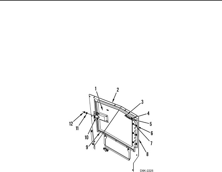
INSTALLATION CONTINUED
5. Install hinge (Figure 3, Item 8), three washers (Figure 3, Item 6), and nuts (Figure 3, Item 7) on left engine
access door (Figure 3, Item 1).
6. Install latch (Figure 3, Item 10), two washers (Figure 3, Item 11), and nuts (Figure 3, Item 12) on left engine
access panel (Figure 3, Item 2).
7. Install four seals (Figure 3, Item 9) on left engine access panel (Figure 3, Item 2).
8. Install left engine access door (Figure 3, Item 1), hinge (Figure 3, Item 8), three washers (Figure 3, Item 6), and
nuts (Figure 3, Item 7) on left engine access panel (Figure 3, Item 2).
9. Install rod (Figure 3, Item 3) on left engine access panel (Figure 3, Item 2).
10. Install washer (Figure 3, Item 4) and new lockpin (Figure 3, Item 5) on rod (Figure 3, Item 3).
11. Close left engine access door (Figure 3, Item 1).
Figure 3. Left Engine Access Door, Hinge, Seals, and Latch.
0185
END OF TASK
FOLLOW-ON TASKS
000185
Verify correct operation of machine (TM 5-2410-240-10).
END OF TASK
END OF WORK PACKAGE