
TM 5-2410-240-23-3
0201
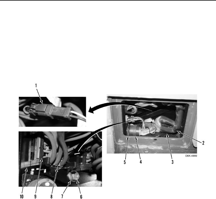
REMOVAL CONTINUED
N OT E
Tag and mark electrical connectors to aid installation.
Note position of tiedown straps to aid installation.
5. Remove three tiedown straps (Figure 3, Item 2) from harness (Figure 3, Item 3), and disconnect connector
(Figure 3, Item 1).
6. Rotate collar (Figure 3, Item 4), and disconnect harness (Figure 3, Item 3) from connector (Figure 3, Item 5).
7. Remove two bolts (Figure 3, Item 6), washers (Figure 3, Item 7), and bracket (Figure 3, Item 8) from fuse
blocks (Figure 3, Item 9).
8. Position fuse block (Figure 3, Item 9) away from front fuse panel (Figure 3, Item 10).
Figure 3. Harness Tiedown Straps.
0201