
TM 5-2410-240-23-3
0201
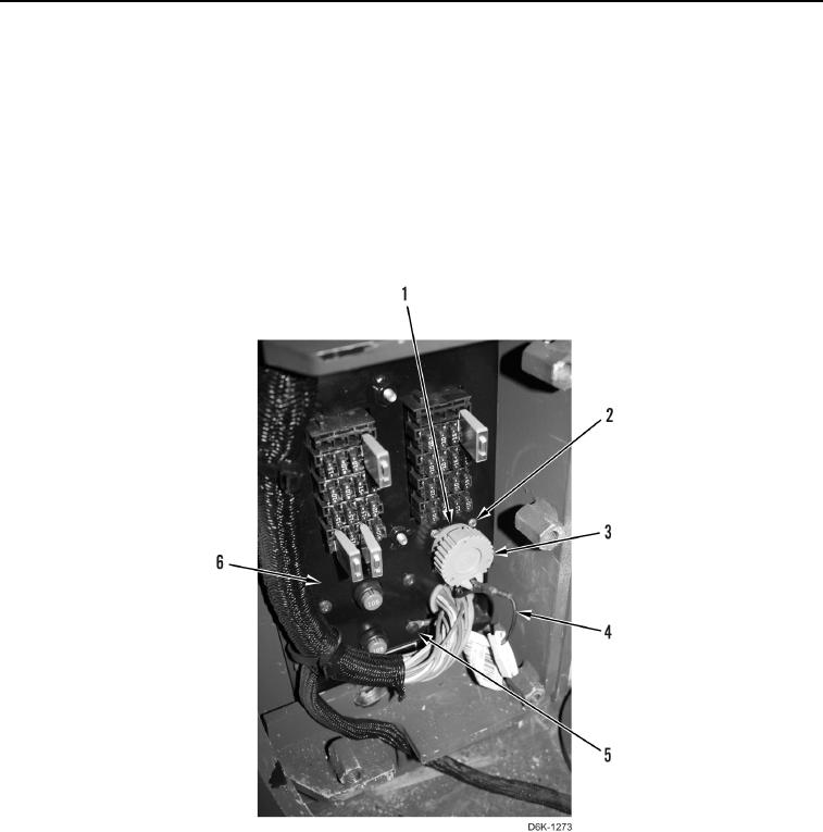
REMOVAL CONTINUED
N OT E
Note position and routing of cable to aid installation.
10. Remove screw (Figure 5, Item 5) and cable (Figure 5, Item 4) from circuit box (Figure 5, Item 6). Position cable
aside.
11. Remove cap (Figure 5, Item 3) and cable (Figure 5, Item 4) from circuit box (Figure 5, Item 6).
12. Remove four screws (Figure 5, Item 2) from circuit box (Figure 5, Item 6).
13. Position plug (Figure 5, Item 1) inside of circuit box (Figure 5, Item 6).
Figure 5. Circuit Breaker Mounting.
0201