TM 5-2410-240-23-3
0201
INSTALLATION CONTINUED
N OT E
Install electrical connectors as noted during removal.
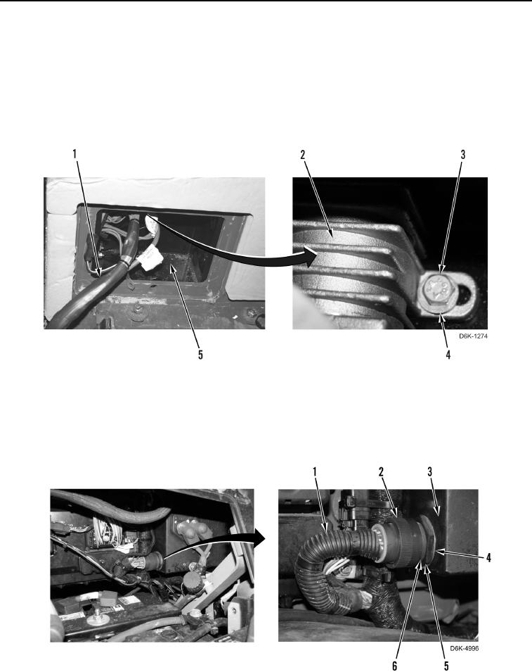
3. Install magnetic switch (Figure 11, Item 2), two washers (Figure 11, Item 4), and bolts (Figure 11, Item 3) on
circuit box (Figure 11, Item 5).
4. Position harness (Figure 11, Item 1) inside circuit box (Figure 11, Item 5).
Figure 11. Magnetic Switch Mounting.
0201
5. Position connector (Figure 12, Item 6) outside circuit box (Figure 12, Item 3).
6. Install washer (Figure 12, Item 4) and nut (Figure 12, Item 5) on connector (Figure 12, Item 6).
7. Connect harness (Figure 12, Item 1) to connector (Figure 12, Item 6), and rotate collar (Figure 12, Item 2).
Figure 12. Harness.
0201

