
TM 5-2410-240-23-3
0202
REMOVAL CONTINUED
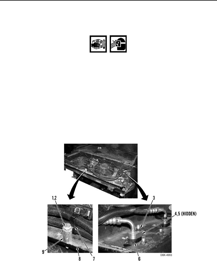
6. Remove bolt (Figure 4, Item 1), washer (Figure 4, Item 2), retainer clip (Figure 4, Item 7), and spacer (Figure 4,
Item 9) from machine (Figure 4, Item 8).
WARN I N G
Use extreme caution when loosening A/C lines. Residual pressure may be present. Wear
eye protection and gloves. Failure to follow this warning may result in injury to personnel.
C AU T I O N
Cap all A/C hoses and fittings during removal to protect against contamination. Failure to
follow this caution may result in equipment damage.
N OT E
Tag and mark A/C hoses to aid installation.
7. Remove two nuts (Figure 4, Item 3) and disconnect two A/C hoses (Figure 4, Item 4) from condenser
(Figure 4, Item 6).
8. Remove two O-rings (Figure 4, Item 5) from two A/C hoses (Figure 4, Item 4). Discard O-rings and position
A/C hoses aside.
Figure 4. A/C Condenser Hose Connections and Hose Retainer.
0202