
TM 5-2410-240-23-3
0202
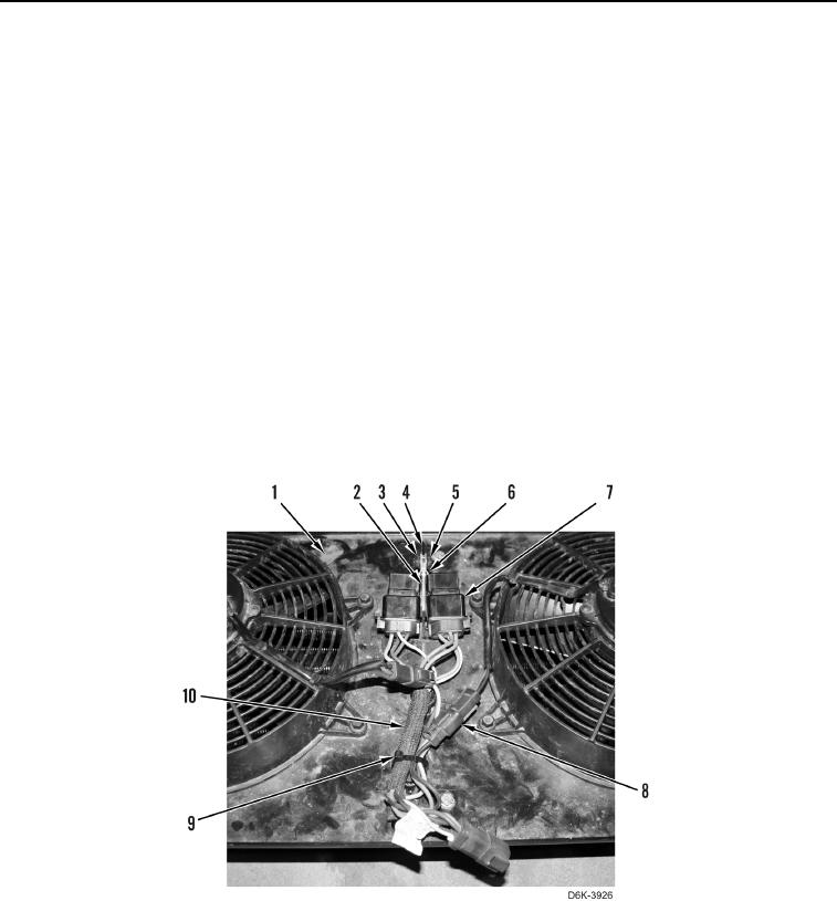
DISASSEMBLY
000202
1. Remove nut (Figure 10, Item 5), bracket (Figure 10, Item 6), bolt (Figure 10, Item 3), and bracket (Figure 10,
Item 2) from bracket (Figure 10, Item 4).
N OT E
Tag and mark electrical connectors to aid installation.
2. Disconnect two relays (Figure 10, Item 7) from wiring harness (Figure 10, Item 10) and position relays aside.
N OT E
Note location of tiedown strap to aid installation.
3. Remove tiedown strap (Figure 10, Item 9) from wiring harness (Figure 10, Item 10). Discard tiedown strap.
N OT E
Tag and mark electrical connectors to aid installation.
4. Disconnect two fan harness connectors (Figure 10, Item 8) from wiring harness (Figure 10, Item 10) and
remove wiring harness from bracket (Figure 10, Item 1).
0202