
TM 5-2410-240-23-3
0202
ASSEMBLY
000202
1. Install condenser (Figure 12, Item 3), 10 washers (Figure 12, Item 2), and bolts (Figure 12, Item 1) on bracket
(Figure 12, Item 4).
2. Install two fans (Figure 11, Item 3), eight washers (Figure 11, Item 2), and bolts (Figure 11, Item 1) on bracket
(Figure 11, Item 4).
N OT E
Install harness and electrical connectors as noted during removal.
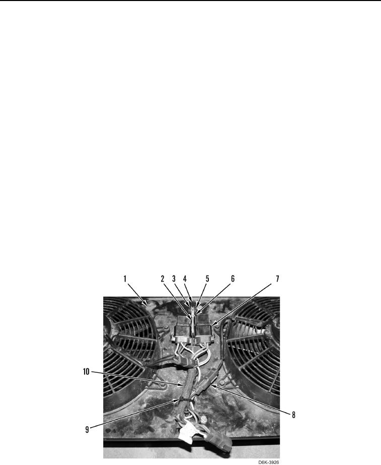
3. Connect two fan harness connectors (Figure 13, Item 8) to wiring harness (Figure 13, Item 10).
4. Position wiring harness (Figure 13, Item 10) on bracket (Figure 13, Item 1).
N OT E
Install tiedown strap as noted during removal.
5. Install new tiedown strap (Figure 13, Item 9) on wiring harness (Figure 13, Item 10).
N OT E
Install harness and electrical connectors as noted during removal.
6. Connect two relays (Figure 13, Item 7) to wiring harness (Figure 13, Item 10) and position relays on bracket
(Figure 13, Item 1).
7. Install bracket (Figure 13, Item 2), bolt (Figure 13, Item 3), bracket (Figure 13, Item 6), and nut (Figure 13,
Item 5) on bracket (Figure 13, Item 4).
0202
END OF TASK