
TM 5-2410-240-23-3
0220
ASSEMBLY CONTINUED
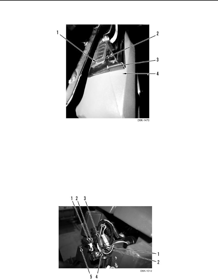
4. Install vent (Figure 11, Item 2) and two screws (Figure 11, Item 1) on plate (Figure 11, Item 3) on dash panel
(Figure 11, Item 4).
Figure 11. Upper Vent.
0220
END OF TASK
INSTALLATION
000220
1. Install dash panel (Figure 12, Item 5) in cab.
N OT E
Install electrical connectors as tagged during removal.
2. Connect action alarm electrical connector (Figure 12, Item 4) to wiring harness (Figure 12, Item 3).
3. Install wiring harness (Figure 12, Item 3) and three new tiedown straps (Figure 12, Item 1) on three brackets
(Figure 12, Item 2).
Figure 12. Rear Dash Panel.
0220