
TM 5-2410-240-23-3
0235
INSTALLATION CONTINUED
N OT E
Install electrical connectors as tagged during removal.
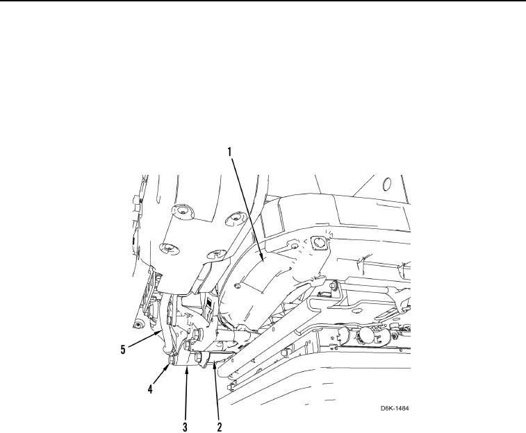
4. Install right joystick support (Figure 34, Item 3) and joystick harness (Figure 34, Item 5).
5. Install retaining right joystick support (Figure 34, Item 3), four bolts (Figure 34, Item 4), and spacer (Figure 34,
Item 2) on seat (Figure 34, Item 1).
Figure 34. Right Support.
0235