
TM 5-2410-240-23-3
0235
INSTALLATION CONTINUED
N OT E
Install electrical connectors as tagged during removal.
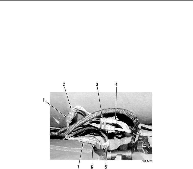
8. Connect seat air suspension connector (Figure 36, Item 6) on cab harness connector (Figure 36, Item 7).
9. Connect seat assembly connector (Figure 36, Item 2) on cab harness connector (Figure 36, Item 1).
10. Connect two seat harness connectors (Figure 36, Item 4) on cab harness connectors (Figure 36, Item 5).
N OT E
Install tiedown straps as noted during removal.
11. Install two new tiedown straps (Figure 36, Item 3) on two seat harness connectors (Figure 36, Item 4).
Figure 36. Seat Harness Connections.
0235