
TM 5-2410-240-23-3
0236
REMOVAL CONTINUED
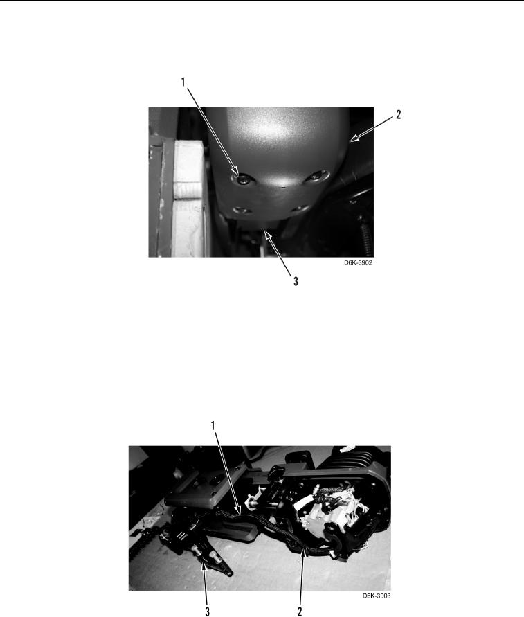
6. Extend right joystick control assembly. Remove four screws (Figure 3, Item 1) and cover (Figure 3,
Item 2) from right joystick control support assembly (Figure 3, Item 3).
Figure 3. Right Joystick Cover - Lower.
0236
N OT E
Note routing of wiring harness to aid installation.
Note location of tiedown sraps to aid installation.
t
7. Remove four tiedown straps (Figure 4, Item 2) and wiring harness (Figure 4, Item 1) from right joystick control
support assembly (Figure 4, Item 3). Discard tiedown straps.
Figure 4. Right Wiring Harness Tiedown Straps.
0236