
TM 5-2410-240-23-3
0236
REMOVAL CONTINUED
N OT E
Note location of tiedown straps to aid installation.
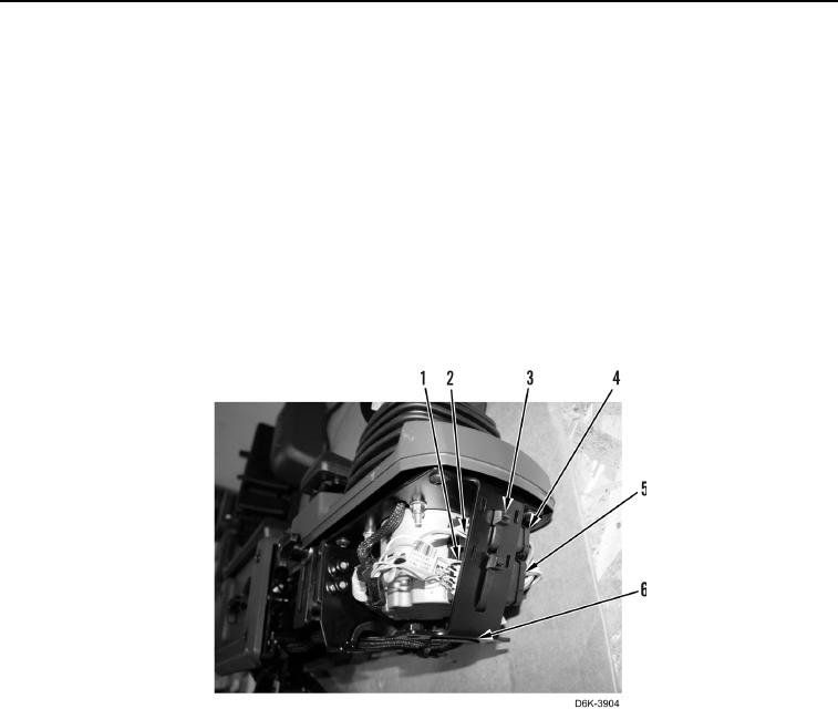
8. Remove two tiedown straps (Figure 5, Item 3) from right joystick control support assembly (Figure 5,
Item 6). Discard tiedown straps.
N OT E
Tag electrical connectors to aid installation.
9. Disconnect first bulldozer control connector (Figure 5, Item 1) from main harness connector (Figure 5, Item 5).
10. Disconnect second bulldozer control connector (Figure 5, Item 2) from main harness connector
(Figure 5, Item 4).
Figure 5. Right Joystick Harness Connectors.
0236