
TM 5-2410-240-23-3
0236
INSTALLATION CONTINUED
N OT E
Install tiedown straps as noted during removal.
4. Install two new tiedown straps (Figure 11, Item 1) on left joystick control support assembly (Figure 11, Item 2).
Figure 11. Left Joystick Connector Tiedown Straps.
0236
N OT E
Install wiring harness as noted during removal.
Install tiedown straps as noted during removal.
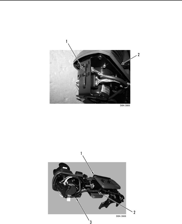
5. Install wiring harness (Figure 12, Item 2) and four new tiedown straps (Figure 12, Item 3) on left joystick control
support assembly (Figure 12, Item 1).
Figure 12. Left Wiring Harness Tiedown Straps.
0236