
TM 5-2410-240-23-3
0236
INSTALLATION
000236
1. Position seat wiring harness on machine.
N OT E
Steps 2 and 3 are performed on the left joystick.
Install electrical connectors as tagged during removal.
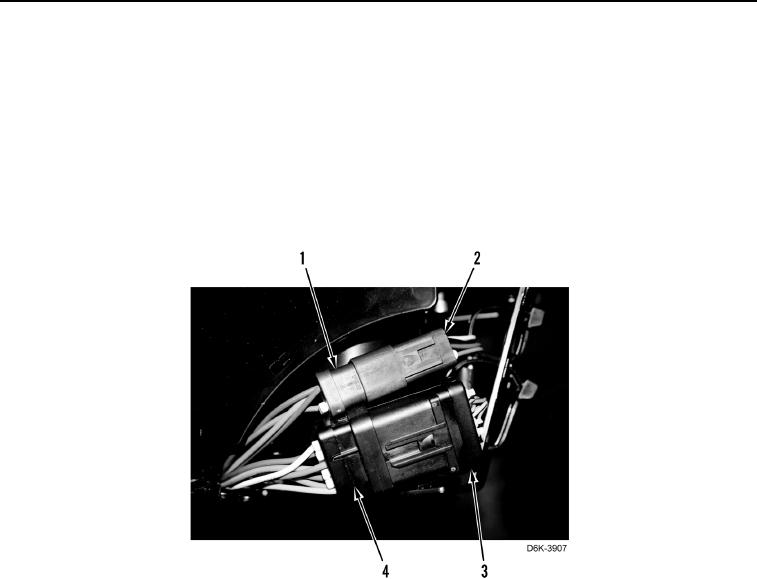
2. Connect horn/speed control connector (Figure 10, Item 4) to main harness connector (Figure 10, Item 3).
3. Connect steering/transmission control connector (Figure 10, Item 1) to main harness connector (Figure 10,
Item 2).
Figure 10. Left Joystick Harness Connectors.
0236