
TM 5-2410-240-23-3
0236
REMOVAL CONTINUED
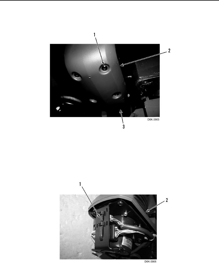
11. Extend left joystick control assembly. Remove four screws (Figure 6, Item 1) and cover (Figure 6, Item 2) from
left joystick control support assembly (Figure 6, Item 3).
Figure 6. Left Joystick Cover - Lower.
0236
N OT E
Note location of tiedown straps to aid installation.
12. Remove two tiedown straps (Figure 7, Item 1) from left joystick control support assembly
(Figure 7, Item 2). Discard tiedown straps.
Figure 7. Left Joystick Connector Tiedown Straps.
0236