
TM 5-2410-240-23-3
0244
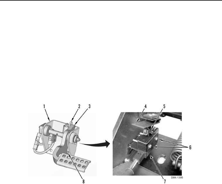
ADJUSTMENT CONTINUED
7. Loosen two limit switch screws (Figure 3, Item 6).
8. Press brake pedal (Figure 3, Item 3) until plunger (Figure 3, Item 8) contacts pedal support (Figure 3, Item 1).
9. Hold position of brake pedal (Figure 3, Item 3).
N OT E
Limit switch is engaged when click noise is heard.
10. Adjust position of limit switch (Figure 3, Item 7) until switch arm (Figure 3, Item 5) contacts spring (Figure 3,
Item 4) but does not engage.
11. Torque two limit screws to 20 lb-in. (2.25 Nm).
12. Check operation of limit switch (Figure 3, Item 7) by depressing brake pedal (Figure 3, Item 3).
13. The limit switch (Figure 3, Item 7) should engage only after plunger (Figure 3, Item 8) contacts pedal support
(Figure 3, Item 1) and pedal (Figure 3, Item 3) contacts link (Figure 3, Item 2).
Figure 3. Limit Switch Adjustment.
0244
END OF TASK