
TM 5-2410-240-23-3
0243
INSTALLATION CONTINUED
000243
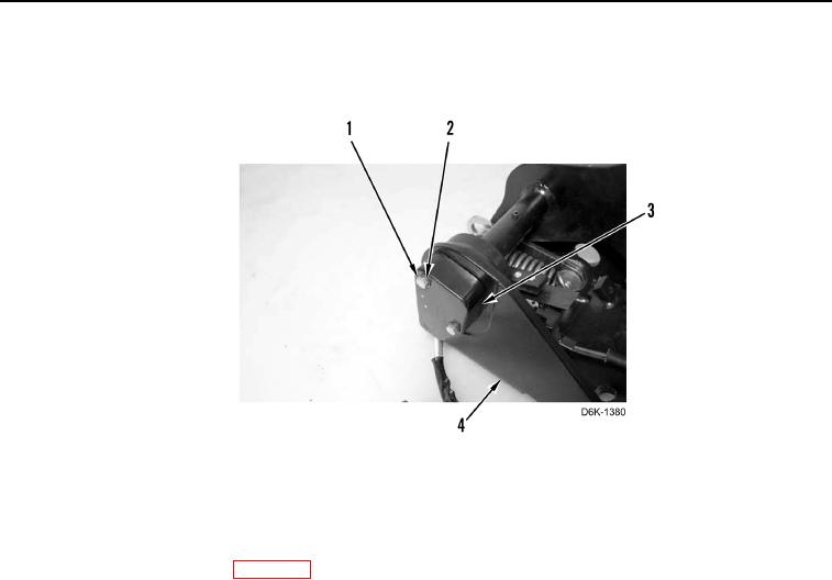
2. Install position sensor (Figure 3, Item 3), two washers (Figure 3, Item 2), and bolts (Figure 3, Item 1) on pedal
support (Figure 3, Item 4). Torque bolts to 20 lb-in. (2.25 Nm).
Figure 3. Brake Pedal Position Sensor.
0243
END OF TASK
FOLLOW-ON TASKS
000243
1. Install service brake control (WP 0242).
2. Verify correct operation of machine (TM 5-2410-240-10).
END OF TASK
END OF WORK PACKAGE
0243-3/(4 blank)