
TM 5-2410-240-23-3
0244
ADJUSTMENT
000244
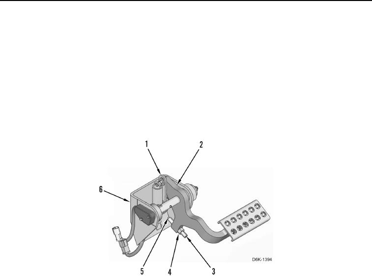
1. Press brake pedal (Figure 2, Item 2), and check for contact between plunger head (Figure 2, Item 5) and pedal
support (Figure 2, Item 6), and between brake pedal and link (Figure 2, Item 1). Loosen nut (Figure 2, Item 4),
and unscrew plunger (Figure 2, Item 3) out from brake pedal until brake pedal can be pressed and contacts
link before plunger head contacts pedal support.
2. Press and hold down brake pedal (Figure 2, Item 2) against link (Figure 2, Item 1).
3. Turn plunger (Figure 2, Item 3) in until plunger head (Figure 2, Item 5) is completely retracted into plunger
(Figure 2, Item 3).
4. Turn plunger (Figure 2, Item 3) out one rotation.
5. Release brake pedal (Figure 2, Item 2).
6. Hold position of plunger (Figure 2, Item 3) and tighten nut (Figure 2, Item 4).
Figure 2. Brake Pedal Plunger Adjustment.
0244